This page contains real world examples for all of the machines presented on this website. If you are looking for a specific machine please select it from the list below, otherwise you may scroll down to view all of the examples.
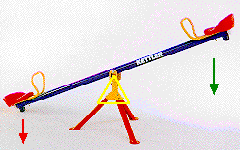
Class One Lever: This photograph of a seesaw clearly shows how a class one lever works. It has been modified to show the fulcrum (yellow triangle) and the direction of the force and load. This seesaw has a mechanical advantage of one because the fulcrum is in the exact center.
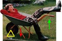
Class Two Lever: This wheelbarrow perfectly illustrates how a class two lever works. The load is contained in the center container, between the fulcrum and the effort force. You pull upward on the handle to get the load to move. This diagram has been modified with force indicators.
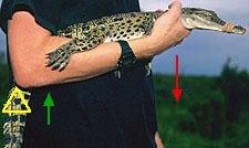
Class Three Lever: This arm depicts the function of a class three lever. Sometimes you do want a machine that gives you distance instead of force, and the human arm is one of those examples. In this force-modified drawing a class three lever is used to lift the load.
Pulleys
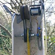
This picture shows how a pulley system works. Electric motors that lift loads often utilize pulley systems in order to decrease the amount of force that the motor must apply. Can you guess what the mechanical advantage of this setup is?
Inclined Plane
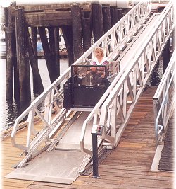
This inclined plane is being used as a ramp. In some cases a ramp is more desirable then a ladder or an elevator. This is because a ramp can give you a mechanical advantage.
Screw
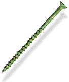
This is just another example of a screw.
Wheel and Axle
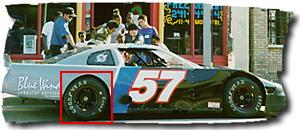
Every car has wheels and this one is no exception. Inside the red box is one of the four wheels that this race car has. The axle is not visible in this drawing.